WIP
text and more configurations to follow.
For years, if a boat had separate batteries for the engine starter and domestic / service use it was normally connected like this, although frequently without the fuses!
 |
| Tradition switching, no longer recommended. |
Charging has to be managed manually (assuming the alternator is connected to "Common") and you had to remember to switch to the domestic battery when the engine went off. The following is better but problematical on the charging side:
 |
| A better basic system with single pole switching. An existing 1B2 switch can be used to replace the main starter switch and the by-pass switch so the net cost of an upgrade would be c £14 plus cables and connectors. |
 |
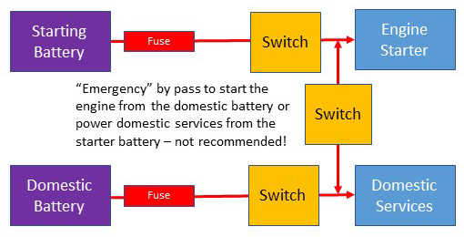
| A flexible easy to understand but slightly more expensive option with two 1B2 switches allows the engine to be started and services supplied from either battery or both. Again charging is problematical. |
Controlling charging.
Charging can be controlled automatically or semi-automatically to various levels of sophistication using several technologies that can be broadly put into three categories:- Digital Voltage Sensitive Relays
- Diodes
- Splitters.
Further manual switches could also be employed but would give even more chances for error and probably not save anything.
Digital Voltage Sensitive Relays (DVSR).
A DVSR, which replaced less reliable analogue voltage sensitive relays, closes at a specified voltage and opens at some lower level which is normally half a volt or so to prevent the switch flip flopping all of the time. In a charging system the DVSR can be used to disconnect a battery to stop it being discharged, usually when the engine is off and the alternator is not producing power, thus protecting the engine starter battery.
There are two types, one will close when the voltage on either side goes over the limit and vice-versa. The other only senses on one side, or sometimes optionally on both.
Car must be taken to ensure that the relay will cope with the currents it could encounter and could include disconnecting under heavy load without damage.
Basic system with two Banks, Solar, etc.
This configuration, with the "emergency" switch open will allow all sources of charging to charge the engine battery and if the voltage on the starter side is above the specified level it will also charge the Domestic Battery.
The more advanced solar / wind controller in this example has two independent outputs which adjusts the output to the needs of the respective batteries, the down side it that there is no priority given to the starter battery.
For easy isolation of the two domestic / service banks the DVSR between them can have its own switched supply to activated, with the switched made the DVSR would be activated automatically with it off the banks would be isolated.
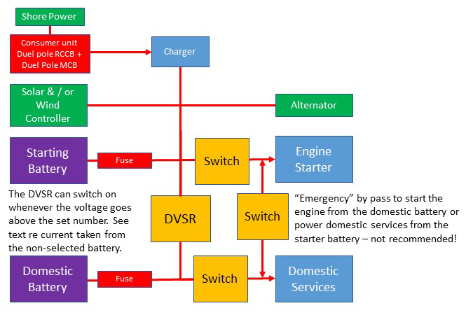 |
| Single pole switching with simple wind and/or solar controller and shore power with DVSR controlled automatic switching for charging. An existing 1B2 switch can be used to replace the main starter switch and the by-pass switch. |
The disadvantages are:
- Because the relay does not open until c 12.8 volts when there is no power being supplied the domestic services will initially take power from both batteries, the starter battery will still have plenty of power available but the voltage will be down a little which might cause problems with a starter solenoid that is not in near perfect condition.
- When the DVSR closes current can flow from the starter battery to the domestic.
Both of these problems can be resolved with manual overrides, most if not all DVSR's have an option to enable it only when a separate line provides power, to prevent problem #1 this can be from the ignition as in the next configuration.
More functional 2 bank system.
 |
| More complex and functional single pole switching with dual o/p wind & solar controller and shore power with DVSR controlled automatic switching for charging. An existing 1B2 switch can be used to replace the main starter switch and the by-pass switch. DVSR should activate bi-directionally. |
The restriction on shore power charging on this configuration can be avoided with the addition of a 2 way low current switch to give the option of activating the DVSR from either the ignition or a separate supply. See the diagram of Sancerre's power distribution with two domestic / service battery banks below for an example
Three Battery Banks
 |
| A complex system with automatic charge control for 2 banks of service / domestic batteries and a starter battery. This would also be applicable if one of the service batteries was forward as a dedicated battery for a bow thruster and/or anchor windlass, which is done to reduce long cable runs to devices using high current but unlikely to be needed on an Achilles. |
For easy isolation of the two domestic / service banks the DVSR between them can have its own switched supply to activated, with the switched made the DVSR would be activated automatically with it off the banks would be isolated.
 |
| Primary power distribution on Sancerre with two domestic / service battery banks. January 2022. |
Diodes
Ease of use, often the cheapest option.
Shared cabling issues.
Issues with alternators that do not self excite.
Heating / cooling.
Voltage drop.
Possible sub optimal charging.
The solar controller may need protection from the other charging systems, some have this included alternatively the diode block may have dual inputs providing the protection.
 |
| Basic diode configuration, demand side switching as per DSRV. If the solar / wind controller(s) has 2 outputs they should go direct to the batteries. |
 |
| Three bank system with diodes. |
Splitters
These vary a lot and can be completely automatic, sometimes intelligent and very efficient.For example it may give priority to the starter battery, test for faults before connecting to a battery, mitigate some of the problems with simple diodes and / or may improve charging performance from the alternator, although not as well as a good external regulator. But they are expensive, up to c £300
May include some basic boosting functions to improve charging efficiency, those that don't will probably have some functionality improving integration with an external alternator controller, see the page "Getting more from your Alternator".
If starting almost from scratch with a clear and definite end state (eg changing from a 2 output to a 3 output device would require buying new) I would be very tempted to get something like the computerised Sterling ProSplit R Isolator to complement my Sterling Pro Reg D Advanced Alternator Regulator.
There are several different suppliers of similar devices and there a lot of variability in functionality and price so it would be sensible to download manuals and installation instructions for all likely options to see exactly what they do.
Cabling issues will be the same as for basic diode systems but other issues may be mitigated check the full spec!
 |
| This is what I would go for on an A9m for long distance sailing a Sterling Power ProSplit and external alternator controller. Solar / wind via a controller with dual independent outputs. Service batteries in parallel to give 240 - 480 Ah as required. |
 |
| Splitter with three battery banks and 3 outputs, in a 2 bank system a solar / wind controller with 2 independent outputs would probably be best connected directly to the batteries. |
Continue to Integrating solar and / or wind generators.
No comments:
Post a Comment