Showing posts with label Upgrades. Show all posts

Sunday, July 6, 2025

Cooker gas supply, maintenance and upgrade.

The rubber hose connecting the Campingaz cylinder had to be replaced because it was a few months from being time expired and when I last changed the cylinder the end was not looking to be in good condition. This was rather earlier than it should have been, it was replaced after I bought the boat it having been picked up on the survey as time expired, then I found that the new hose was already almost 2 years old so now it was almost out of life.

The gas regulator was also looking ropey and when I checked up it has a 6 year replacement life (5 years is more common and 10 years the maximum quoted by The Cruising Association technical team). I couldn't see a date on it but as I have had the boat for 8 years it was clearly time to replace it, also the previous hose had been over ten years old when replaced and I would have thought you wouldn’t install a new premium regulator without replacing a cheap piece of rubber hose.

As both were in need of replacement I decided I might as well do the job properly and fit both an automatic shut off valve that closes if the gas flow it too high or pressure is low indicating a leak in the system plus a remote gas valve close to the cylinder, both are in the vented gas locker so that when the cooker is not in use all of the pipe work inside of the boat and the cooker is isolated at the press of a button. 

The remote gas valve is only open when power is applied so turning off the domestic power will isolate the gas when leaving the boat even if the local "gas on" switch is left on. That switch is illuminated when on as a reminder to turn it off when not using the cooker. It also saves bending down to reach the manual gas cock. 

I also have a hand held detector for tracking down suspected leaks
and false alarms from other sources. All should have one!
Fitting the rather large Cleese valve in the locker was tricky as there is not a lot of room and it must be clear of the cylinder so that the knob can easily rotate to shut off the gas, but it just fits providing the cylinder is properly located in its holder. Also the hose needs a smooth curve off of the long hose tails to prevent kinking.
A little cramped but it works and with a longish bit of hose
getting the cylinder in and out is no problem.
The Viton / Shako solenoid valve is available in two versions, one with a short pair of leads, one with a DIN connector, the latter is likely to be preferred as it avoids an additional cable join and it is more robust. There are three connections, the lower is marked earth but is not used in a DC installation, above that the left connection is positive and the right negative, neither are marked but see How To Wire A Shako PU220AR-02 Solenoid Valve – dropController
Press the red button to turn the gas on and off at the gas locker.

Monday, December 9, 2024

Installing a powered USB hub and why

Another post to while away some winter hours, and incidentally to keep the boats documentation up to date. 

Updated after installation was complete.

I use an iPhone and iPad, everything here should also apply to Android devices but I am not familiar with them, research indicates that the the Kingston Hub would not have the problems with Android that I had trying to use it with an iPhone.

I have had a powered USB hub on the boat from the beginning, the reason for the upgrade is my increased use of the PC on the internet. For reasons of economy I have generally restricted my internet use to the unlimited (but "throttled") data only sim in my iPad occasionally using the laptop through its wi-fi hot spot, this year with prices dropping I put a meaningful amount of data onto the iPhone account (and that is from now on also unlimited), the problem then became the wi-fi connection drooping when briefly inactive which was a pain in the neck.

To solve that through 2024 I tethered the laptop to the phone using a USB cable which works well and also gives easier data sharing between the laptop, phone and chart plotter, the problem is then remembering to reconnect the phone to its USB charging point or, without power from the PC, the battery will run down, that only happened once but that is one time to many so to sort that the phone needs to connect to an always on powered USB hub that can also provide charging. 

I was also using an unpowered hub daisy chained to the 4 port powered one and there were lots of wires in inconvenient places.  It was time to upgrade.

Installation should have been straight forward although choosing and getting power to the hub needs some thought and research but Windows 11 threw some curve balls at me as did my choice of the Kingston 7 port hub and I had to redesign on the fly.

Final configuration (updated Oct 2025). Click to view.

Connections and Services

For a lot more detail on integration see SV Sancerre: Wi-Fi networking and application integration on Sancerre remembering this was written before the upgrade to a 7 port device, tethering the phone etc.

iPhone (or any smart phone)

  • Connects the PC to the internet when a 3 or 4G connection is available.
  • Using Garmin Active Captain and wi-fi, transfers routes from the navigation software plus software updates and community notes from Garmin to the plotter.
  • Smart notifications such as SMS texts, Facebook notifications, etc. are transferred to the plotter by Bluetooth.

AIS

The Garmin AIS unit only puts AIS information onto the NMEA 2000 network and keeps its GPS data to itself which is annoying as with its external antenna it has the most reliable GPS position on the boat (although the internal aerial in the plotter has not lost a signal yet). 

Update: further investigation of the AIS 600 documentation indicates that the GPS information is not put onto the NMEA 2000 network but the minimum recommended GPS sentence is put onto the NMEA 0183 output. I am checking to find if this is done in parallel to the 2000 output (I guess it will be) and the easiest  way of accessing it, perhaps with a dry cheap (< £20) serial to Wi-Fi converter that would put AIS onto my iPads.

However there is a USB port for set up and diagnostics and when I installed it I suspected that it would use standard NMEA 0183 protocols; why invent new ones when standard ones exist and you already have code for dealing with them? And so it proved, so the USB cable is permanently connected to the hub, the Garmin USB driver presents a logical COM port to applications and those that are capable can use the differential GPS / EGNOS fix (& Glonass), I mainly use this GPS with SeaPro 3000 and Memory-Map but it can also be useful for Google Earth and other applications.

GPS

As backup I have two USB GNSS devices:

  • A GPS & GLONASS dongle (they are less than £10 with support for GPS, GLONASS, WAAS/EGNOS, etc.)
  • A unit that supports two channel GPS (USA), GLONASS (Russian), Galileo (European), Beidou (Chinese) and QZSS (Japanese but Asia Pacific only) plus WAAS, EGNOS, MSAS and GAGAN. With four systems available in Europe at least one should be available! Crude jamming is likely to impact all, if necessary any of the systems can be turned off.  Galileo is the most accurate, about 3 times better than GPS at c 1 metre (testing it is showing an accuracy to better than half a metre) but that is pretty much irrelevant on the PC. Units with Galileo support under £100 are hard to come by (2025), I got one from Germany (£70 including postage etc.), marine units with NMEA are close to £200, some a lot more.
These allows the PC systems to take over position fixing if the plotter and NMEA2000 network should fail. It is also occasionally useful when switching between SeaPro and Memory-Map, perhaps to use the Antares charts or to check a route on the standard Admiralty raster charts. The AIS com port can not be shared between applications and even if you close one application down the PC is likely to think the port is still potentially active and the newly launched software gives an error. 

I set Memory-map to use the USB services and SeaPro to use the AIS output and I can then have both active at the same time or switch between them without problems. In the event of a failure I can easily change the configuration to allow SeaPro to use a USB GPS or Memory-map to display AIS.

GND

Some of the many re-sizable windows available
on a connected PC with Nexus. They can be moved
around to fit with or on top of other windows.
Is a bridge between the wind instruments and NMEA200 but also runs as a NX2 server for Nexus software providing most of the information from the NMEA 2000 network down a USB connection, unfortunately that is not usable by SeaPro or Memory-Map but free software allows you to display it on the PC. I can't remember when I last used it but it is free so it might as well be connected.

NAVTEX

I now rarely use it as the met office forecasts are readily available on their website and navigation warnings from the Admiralty website and they are also broadcast by the coastguard but venturing further afield it is a useful backup or replacement for IridiumGo (which does not carry the nav warnings).

USB-3 connections

This can be used to connect various ancillaries that benefit from a fast transfer rate such as a card reader (not included on my new laptop) or DVD or to plug in an iPad. This is also a powered port so will do a better job of supporting an iPad.

Power

This might be the tricky bit. Powered hubs are intended to run from the mains, using an inverter, even if you have one installed, does not make a lot of sense - converting 12V DC to 240V AC and back to whatever DC voltage the hub uses.

However all is not lost, over the years makers have been standardising many PC related items to run off of 5V DC as used by USB devices, even my latest lap top when on mains uses a 3 Amp 5V supply connected to the PC by a USB-C plug (for some reason the car 12V lead and converter to 5V uses a different socket). 

My original 4 port hub came with a 240V 13Amp USB charging plug and a USB-A to centre pin lead, I just replaced the 13A plug with an off the shelf 12V to USB socket available from the chandlers and elsewhere.
 
The 7 port powered hub. Preferred to others as it is small and does
not have unwanted switches or lights. It is USB-3 so fast and
2 ports will provide additional power with automatic detection.
The voltage is marked by the socket on the end. Not as it turned
out a good choice if connecting an iPhone.
This time I could not find one like that and online suppliers don't seem to specify the intermediate voltage of there units, but if they have a detachable lead the voltage should be noted beside the socket and it should also be on the power supply; usually in almost microscopic lettering with the rest of the spec. So the trick is to expand photos to read the info from there. I found that the Kingston units were definitely 5V, the power cable is captive to the power supply so in a worst case I would cut the cable and splice it to a USB cable, fabricate from scratch (but there is an easier route, see below) or look for one, but the cable on my old hub does the trick. 

As it turned out it would not work with the iPhone so it was relegated to be a passive hub and the topology changed. Fortunately the 4 port hub I had been using as a passive hub could be powered and was USB3 compatible so that was promoted to be the powered hub. Connecting the power was straight forward using a USB A to USB C cable.
12V to 5.1V step down unit with
fast charge.

Using an off the shelf USB socket for the power source does have a down side, all of the ones I have seen working from 12 volts deliver 2 Amps, useable but not that good for recharging a phone or iPad and would be marginal if an iPad and phone were connected a the same time. The solution is a step down unit, these are readily available on eBay and elsewhere, most deliver 3 Amps for 15 Watts nominal costing £5.89 including postage and is available with USB or  bare wire output that would be easy to connect to the power lead that comes with a hub. I found one that delivers 5 Amps through up to 4 female USB-a sockets @ £6.91. Whilst not as fast charging as a good mains powered charging station  I'll settle for a potential improvement of 2.5 times over standard.

There are 4 outputs from the unit so one powers the hub (and phone) and another has  a male to female USB A cable for charging other devices, in my case, several lights, lighters for the gas, battery charger for the camera and iPads if I should let them run down.

I prefer things fused and switched so the step down unit has both, getting power from the low power switched bus behind the electrical panel. It will normally be left switched on at the panel and will go off when the master switch is off, but if I am a long time at anchor (quite likely) and short of power (unlikely) I can switch it off to save the small parasitic current it uses.

The nav station (before tidying up redundant wires and covering
up the rest) with recently updated electrical panel and the PC
connected to the internet via the iPhone and USB and running 
Memory-map with a GPS fix from the dongle, and Nexus Race
software showing 3 virtual instruments at the top of the screen,
iirc heading from the Raymarine autopilot sensor plus wind
speed and direction from the Garmin sensors

Windows 11 Issues

These were very frustrating and together with the problem with the Kingstone hub took several hours to resolve, particularly as the Windows issues made fault finding difficult and more prolonged as I had to keep rebooting because of the first issue.

Com Ports:

First Windows 11 consistently allocated COM3 to a newly added USB virtual serial port connection even when it had previously allocated COM3 to another device, this did not happen under Windows 10. This confused the applications as the COM port can only support one at a time. Google AI says this does not happen, but it can and deeper research after I had worked round the issue confirms this and gives some of the reasons why. I did not follow though with that as its now working but there were references to changing registry settings as a fix.

To fix this I first identified which of the two "COM3s" was the newly added one (IIRC it was always the 2nd on the list) then I changed the COM Port number manually and rebooted and it would work, fortunately as it is a new PC I knew the highest com port already allocated. 

I don't have a device at home that uses a virtual COM port so I can't give precise instructions on how to do this but you start by right clicking on windows start, select device manage, select COM Ports (the devices have to be connected to see them), then the one you want to change, then look for something along the lines of "settings" where there will be an "advanced option" where you can change the port number, it will give an error message that the port is in use, ignore this as it is the first COM3. Then reboot, selecting scan for hardware changes might work but I would want to reboot to check that the fix had taken so there is not much point.

Garmin drives and security settings:

The Garmin drivers for virtual Com Ports for AIS and GND units are not compatible with a particular security feature of Windows 11 (these drivers are also implicated in the COM port issue but they are the latest available), the error message gives the necessary info to turn this off (it may be an option I opted into that defaults off but I can't be certain, the PC is not that new).

Friday, February 16, 2024

Fiddles

Hopefully the new removable fiddle on the inboard side of
the table will....

prevent a repetition of this which happened at anchor at the
Skerries (IRE)
.

Monday, October 23, 2023

Installing a holding tank - Design.

With the slope of the hull and the web
supporting the aft lower shroud fitting
there is not a lot of room behind the toilet
and none under. Securing a sometimes
heavy tank would also be difficult.
To be more environmentally friendly and to avoid some trips ashore for "comfort breaks", I have been toying with the idea of a black water holding tank for several years but its not easy because of space constraints. 

Older boats are not required to have holding tanks in most jurisdictions, regulations vary by country but generally waste can be discharged when more than 3 miles offshore, perhaps unsurprisingly (in 2023) there are no restrictions on discharging waste in UK coastal waters although many marinas and harbours have local regulations or by-laws banning discharges.

The space behind the toilet could take a tank but to be anywhere near a useful size it would have to be bespoke and therefore very expensive, it would also be difficult to fit to the sloping hull, difficult to plumb in and I would loose some small but handy storage space for toiletries and loo cleaner. 

Underneath what was the port berth in the forepeak or under the port berth in the saloon would both easily take a rubber tank but they are difficult to secure and I don't fancy a rubber tank full of sewage anywhere in the boat. Again solid tanks would have to be specially made and both options would require lots of expensive plumbing with diverter valves, pump, etc..

More realistically with the forepeak no longer having berths, a tank could be installed there on the port bulkhead next to the heads. 

If the tank bottom is high enough above the waterline and the pipe work reasonably short and not too bendy this could be emptied overboard by gravity and, with the appropriate fittings, optionally by pump out. 

Again space and cost are issues; an excellent vertical tank is made by "Tek-Tanks" it is made to order in standard sizes with inlets and outlets positioned to order. There are problems, space is at best barely adequate for the smallest 40 litre version, there might not be sufficient "head" for it to drain correctly, and the tank without hose tails is £389. A similar but much cruder design by Nuova Rade is only £159 but again it would be difficult to fit and drainage could be an issue. Both options could be made to work with a lot of plumbing and a pump to drain the tank as sea but it gets expensive and complicated.

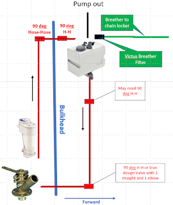
Schematic of the planned installation.
I gave up on the project the last couple of winters but this year I found a 25 litre horizontally orientated tank by Vetus that is much shallower so gives more space for installation above and below and a better head for drainage, still £270 but unlike the other tanks that does included all the hose tails bar one.

The height for gravity drainage looks to be OK even if a couple of elbows are required, especially as the electric pump and Macerator does a better job of breaking up solids and paper than a manually operated toilet.

When offshore the seacock is left open and waste goes straight out, in sensitive areas the sea cock is closed and the waste accumulates in the holding tank later be released at sea or pumped out.

If in use the gravity drainage proves not to work there is room to install the new Henderson Mk5 pump I happen to have (its a long story) between the tank and the seacock. That would be a pain at sea requiring manual pump outs but it would work and I could add a diverter valve and additional pipe work.

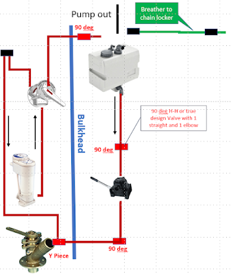
The back up plan (see next post for an updated final version).
Outline plan for the bulkhead mount.
Most of the components are on order and should be here by early next week, the rest I'll get locally some after trial fits, and I'll start the installation when there is some decent weather to visit the boat.

Sunday, October 22, 2023

Installing a holding tank - Installation, Day 1.

I'm glad that I did not try using a 40 litre tank or even the 25 litre vertical, at best it would have had very complicated pipe work, needed new and tricky to build head lining and would probably not have self drained properly. 

The bad news was that due to a number of factors, mainly positioning of the filter and the length (depth) of the deck fitting for pump out, I had to put the tank lower than I had hoped so gravity draining was still going to be problematic and would probably not have worked at all on starboard tack so I switched to "plan B" and am fitting a pump, diverter valve and a stop valve between the tank and the discharge pump. The existing inlet pipe work and the anti-syphon loop can be reused without modification which will save some time and money.

The end of a long days work (finished at 19:00),
the pipe to the filter needs a clip to hold it up so it
would drain back to the tank if any water got in.
Apart from that I made good progress, 

  • The panelling in the heads is out and most of the black mould behind removed, the rest will go when I have moved some pipework.
  • The tank is mounted with a substantial block underneath that is bolted through the bulkhead to support it.
  • Inlet connected at the tank end and taken through to where the diverter will go.
  • Vacuum pump out piping completed, the head lining hides the deck fitting and just needed a small piece taken out on the aft edge for the pipe to go through. 
  • The filter is fitted to the bulk head and the inlet pipe fitted, it is close to the head lining but to change the filter the headline can easily come down, its held up by Velcro, and there is oodles of space above (where I had thought to put the filter).

The pump will go under the former port bunk, I have it home and it's now fitted to a mounting board ready to install. The locker lid has been shortened to open past the tank, the off cut will go back in with the waste pipe going through it. I'm now waiting for the diverter valve to be delivered and I should be able to finish the job in another long day.

The main problem fitting the tank lower was difficulty in siting the
pump out fitting to get the pipe to the tank without interfering
with the inlet pipe or getting in the way. In the end I put it on the edge
of the coach roof rather than on the deck. Further inboard would have
given a good lead but then there would be nowhere to put the filter
with the bottom of the unit and pipes above the tank and outlet in
the chain locker.
The fitted unit, I was quite pleased with the neat fit to the
Treadmaster anti-slip pad.

As fitted.


Installing a holding tank - Installation, Days 2 & 3

It was a bit of s struggle getting hoses on, even with lots of hot water, but I got there in the end.

There is a "Y" junction bottom left leading to the
seacock,  the holding tank outlet pipe going behind
the bowl, the direct outlet is waiting to be cut and
connected to the diverter via the anti-syphon loop.
The green pipe is for the automatic bilge pump
Getting the diverter straight and fixed to the panel
was the biggest struggle mainly due to lack of
room plus stiff pipes and pipe connections that
would not rotate (with jubilee clips slack).
The finished job. The board left is a drop down table,
rarely used now that I wear a beard so don't need it
shaving using the mirror out of picture right. If I
venture into the Baltic or some other areas I will
have to put an eye on the panel to "lock" (probably with
a cable tie) the diverter to feed to the tank as is required
in places to prevent an accidental discharge.
The holding tank and filter fully plumbed in, the breather goes
to the chain locker as there is insufficient freeboard to put it
through the hull without a high risk of getting water in the filter.
The Henderson Mk 5 pump in position with the ball valve left.
All plastic components are by Trudesign, the seacocks are genuine
bronze (not  DZR Brass)  by "Blakes". The pump is capable of
emptying the tank in less than 30 seconds. Lots of jubilee clips,
 doubled for all connections below the water line or hidden are
needed for piece of mind and to keep surveyors and insurance
companies happy.
The hatch, installed when I converted the forepeak to a wet area
had to be butchered, I can still get my spare washboards in the
locker but I'll have to find somewhere else for the spare tiller. For access
I'll need to keep this area reasonably free of obstructions so things I might
 need quickly or regularly are going to live in the locker.
All together it took about 3 days but I had the advantage of my work some years ago replacing the original vanity unit and installing panelling and the electric conversion to the toilet.

Servicing the clean water input side of the unit,
the output side was not as straightforward.
As I was working in the area a deep service on the 5 year old macerator seemed to be a sensible idea, unfortunately it as not straightforward; two slot headed machine screws were unmovable, I ended up bringing it home, drilling off the heads, disassembling, bending the 650mm M5 machine screws through c 90 degrees and using the bend to get leverage to free them after applying lots of penetrating oil. 

Fortunately nothing was damaged so it only cost a couple of bolts, lots of swearing, several hours and a "wasted" visit to the boat when I tried to do the service whilst on board.

Sunday, December 26, 2021

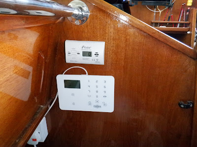
Carbon Monoxide Detector

The alarm sounds at a variable level dependant on average 
levels over a period but not below 30 ppm.
Something I have been meaning to fit for a while but the need was highlighted during my very cold trip in April and May when I was using the cooker a lot for cooking and the grill occasionally to keep warm.

I finally did it and trials show that with the Dorade and washboards vents open the oven and oil lamp registered 0, a test with a small gas fire got it up to 15 ppm after 45 minutes.

Not shown is a smoke detector - just in case.

Thursday, December 16, 2021

Heavy weather and Storm jib rigging.

With calm weather on Wednesday I was able to check the fit of the new heavy weather jib.

The Dyneema inner forestay (reeved through the original starboard
jib halyard sheaves) is tensioned from below with 4:1 tackle going
 back to one of the 23:1, 2 speed winches at the aft end of the cabin roof.
The stay, block and snap shackle have break loads of more than 2 Tonnes
the shackle on the tackle is a weak link to protect the rest.
I added the u-bolt for this and to attach the main preventer for maximum leverage.
The heavy weather jib is normally hoisted with the
spinnaker halyard (removed for the winter) rather
than the wire genoa halyard.
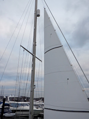
The stay should clear the furled headsail but I can move the tack back a little if necessary. I was cautious when I measured up, particularly to clear the radar reflector. The sail is 12.1 square metres, looking at in place I could probably have had it made c10% bigger by lowering the clew a little and lengthening the luff and leach but this way at least the foot should clear of waves.

Sheeting


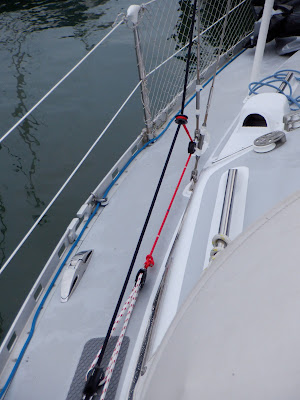
The genoa sheets need to stay on the sail when the heavy weather or storm jib is in use, previously I had a block on the toe rail and a non adjustable tweaker to narrow the sheeting angle, that was not going to work well with a larger sail likely to be used fairly often, I therefore put a dedicated block ahead of the genoa sheeting track, the sheets go back to the large spinnaker winches on the cockpit coaming, the port one via the toe rail to get a better angle onto the starboard side of the winch. 

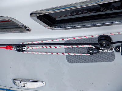
A low friction ring is used on a barber hauler system with a three part tackle going back to a cam cleat on the side of the coach roof. The front block goes to the bottom of main shroud and attaches with a  snap shackle so that when not in use it can be clipped to the mast keeping the tackle clear of the walk way. The loose part of the dedicated set of sheets go into a bag on the mast.
The Barber hauler set up. It should not need to be
hauled in this much, note the whippings at intervals
to speed set up.
Sheet block on the right just ahead of the genoa sheeting track.
The "Treadmaster" pad intended for steps, protects the deck from
the blocks and should reduce any noise if they move.
Leaving Fowey for the Fal, 2023 with just the
heavy weather jib, later the wind was gusting F7
.
More on storm jibs etc can be found on my earlier piece "Storm Jibs".

Saturday, November 20, 2021

Rebuilt bin locker and a repair.

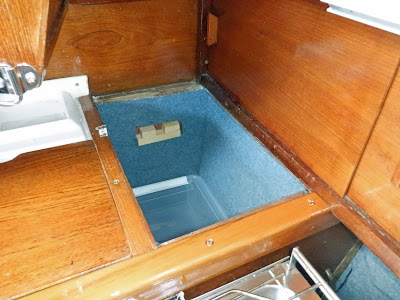
Sancerre once had a built in and very inefficient electric cool box aft of the cooker, this was not working when I bought the boat and probably had not for years. With all of the insulation and voids around it a lot of space was being wasted.

Lots of wasted space.
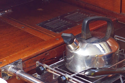
Replacing the fuel tank and moving the water tank (see previous posts) meant working under the sink unit so I decided to sort this out at the same time.  The capping piece on the front / top of the unit had been damaged by a previous cooker so that could also do with replacing.
A big crack & unsightly holes in the Teak capping piece.
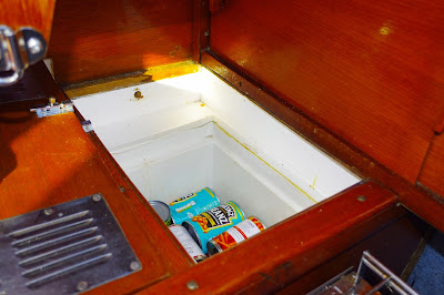
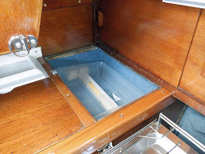
Lots more space, the bin is hardwood marine ply, epoxy coated
on both sides with carpet to deaden sound as things move about.
 The timber blocks support a tray for ready to use items, fresh veg etc.
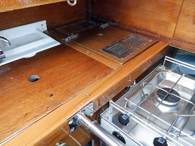
The new Teak capping pieces cost more than the rest of the job together, even sourced as simple planed all round (PAR) timber to a standard size, fortunately I have a bench router to round the edges saving machining costs.

Job done and looking better. The cup holder is a little lower than
before and out of frame.

Wednesday, October 27, 2021

New guardrail stanchion bases

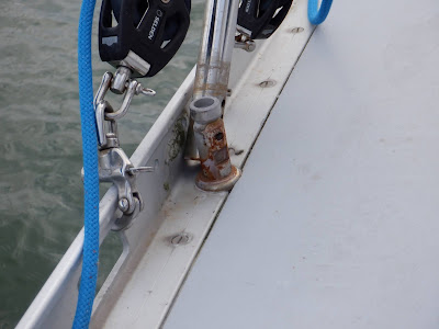
The boat had new stanchions when I bought her but they have never worked correctly leaving me with slack guardrail lines. 

Once I had tightened it up the main bolt and put on a lock nut (omitted by the yard) the base was stable but however much you tighten up the connection between the stanchion and the base it went slack in no time.

One of the 8 stanchion bases.
Fortunately I found that the stanchion was a standard 25mm so I was able to put this fitting over the top of the original.
Four of the stanchions were fixed on the first visit before near
gale force winds and some rain made it too much like hard work.
Naturally it was not that simple, the one I used for testing I purchased a couple of years ago for the cooker crash guard (see pic in the previous post) and it was a nice snug press fit. This batch were very slightly smaller and needed a serious lump hammer to get the stanchion in, but I ended up with a nice rigid stanchion and tight guardrails.

Friday, October 8, 2021

Replacing the Cockpit Locker Floor, Part 3 + Installing the new Fuel Tank.

Day 1 of the installation and the floor is in but not secured, the new water tank and plumbing was done and the water pump & filter moved.


Day 3 and the job is almost done, just the other part of the slide bolt
needs to be found and fixed (its reused).
I thought for a moment I had specified the tank to be a little too long or too high but with a great deal of fiddling and even more swearing it went in. The floor is screwed down all round and the softwood sections forward and inboard are fixed sideways so the whole lot should stay in place in the event of an inversion.

The lashing points are for fuel in cans, probably a max of 40 Litres in 10 Litre cans as my 20 Litre jerry cans are too tall, leaving no room for buckets to go in on top. That is somewhat less than previously but the tank effectively holds 10 - 15 Litres more than the old one which partially compensates and in total will still give 70 hours endurance, in reasonable weather that would be at 5.5 - 6 knots and 385 - 420 NM range (or quite a bit more with a clean hull and / or in dead calm waters).
I fitted a new fuel filter with a clear lower section and drain in case of water contamination. The original filter is in the engine compartment and would be almost impossible to get at when at sea unless it was dead calm, not good if you got the fuel bug. The fuel bulb made bleeding the system dead easy. The engine started immediately although I want to run it for another 30 minutes before leaving the mooring, just in case.

The big electrical cable is from the fuel sender to a NMEA converter so fuel level can be displayed on the plotter and one of the wind instruments.

The rope hanging down (see also the 2nd pic) is my method of securing the locker from thieves and backing up the latch in heavy weather, the end of the tackle goes to a cleat inside of the boat, a similar system runs to the Lazarette hatch covers.
On my last sail I finally found one of the leaks into the compartment which appeared to be from the bilge pump, but when I got it out I found that when the new mainsheet track was fitted (before I got the boat) someone had drilled through the bilge pump outlet pipe so on the odd occasion I used it bilge water sprayed out, but unless the hatch was open which would be rare because you would normally sit on the hatch when pumping, you wouldn't know. Fortunately there was enough slack so I cut off 6" and refitted.

Update 6th November.

Unfortunately it didn't work. Last week I decided to do a long running test (rather than the 10 minutes or so after installation) and the engine stopped after 10 - 25 minutes on several tests. It appeared that the bulb primer was the problem.

Ron (a fellow Achilles owner and serial restorer) consulted with Roger (Dehler 41, "Blue Magic") who immediately recognised the problem which happens on some trucks, the solution should be to have the bulb vertical with the flow downwards so that gravity would help open the non return valve. The bulbs pump fuel best the other way up but does pump in all positions.

Unfortunately that didn't work, the Yanmar 2GM20's low pressure pump is just not powerful enough to open the valve on that brand of bulb (Osculati), this creates a vacuum in the fuel system and the engine stops. The first fuel filter is now connected directly to the tank and on the first test of the engine ran for an hour before I got fed up with diesel fumes blowing into the boat.

So a device to save a few minutes once a year when the engine is serviced or if it runs out of fuel, cost me a day and a half and a 160 mile round trip to the boat 😞.

Update Early December:


Even the above did not work properly, after a week of non-use the engine failed after 10 minutes but then ran for an hour after bleeding. This was getting serious and needed to be fixed quickly as I had to motor a couple of miles upriver to be lifted out on the 17th. I remove the old fuel filter, tap (there just might have been an air leak from the tap although it was not a joint that I undid and there was no fuel leak) and all extraneous pipe. It can't now get any simpler for a tank with a top take-off. It worked, I test ran for an hour a week later before moving to the RAFYC pontoon and again a couple of days later before going upriver and no problems. But I think I'll run another 15 -20 minute test as soon as the boat goes back in the water, which in any case is recommended procedure after a winter lay up.

Update March:

The new pipe work etc. retained fuel for 3 months of non use and after a 20 minute test I motored down river with no problems.

Monday, October 4, 2021

Replacing the Cockpit Locker Floor, Part 2.

The new fuel tank arrived earlier than expected but typically the timber was rather later, but it is now built and ready to go.

New cockpit locker floor built to support the new fuel tank and cover the new water tank. The plastic rulers under the tank are there to ensure that the tank will not sit on any water that pools under the tank and allows any water that might get in to drain away into the bilge (the drain holes are not visible).

Three bolts press against timber spacers
to help locate the tank firmly in place at
the base.
The floor has to support a heavy stainless steel tank with 70 Litres (almost 70 Kg) of fuel in it and another c30 litres in cans. And do that in a heavy sea. It also has to hold the tank, cans and at least part of the weight of a full water bladder tank (which is up to c 40Kg) if the boat turns up side down. That would not have the same shock loading as a very rough sea but fixing the floor down is a challenge especially as it is very hard to reach the edges through the narrow hatch quite away above. More on that to follow.

The platform is made from a seriously expensive hardwood ply with Lloyds certification for structural use in high risk environments. It is much stiffer than "normal" marine ply, will take higher compression loads and has a 25 year guarantee.

It is made in 2 main sections rather than the three of the previous one and my initial design, with the hatch section removed I should be able to get the larger section in (fingers crossed). 

It is 9mm thick with the beams under 11mm. Other timber is reclaimed mahogany and teak with spacers made from Sapele left over from when I replaced the headlining. Fastenings, retaining pieces, etc. are in marine stainless.

The whole is covered in epoxy rather than varnished for better durability and the beams are screwed and glued together with glass tape bonded over for additional strength. Very much over engineered, I hope.

The hatch is to give access to the new bladder water tank under.

Each strap is strong enough to hold the tank in place - assuming the timber holds which with reinforcement under it should. The forward strap will be secured to the  bulkhead. 

The hole in the platform back right is for the water filler, that front right is for the fuel pipes to and from the engine and the one front left is a breather to hopefully keep the lower section reasonably dry and to help the water  tank expand as its filled.

Installation of this and the new water tank is going to be a long job and if the weather is good will hopefully start later in the week. 

Click here for the next stage.

Tuesday, September 28, 2021

Replacing the Water Tank and Cockpit Locker floor - Part 1.

As mentioned in a previous post I am building a new food storage bin and moving  the water tank from the forepeak to under the port cockpit locker, reducing weight forward and the length of pipe work required as part of a project to replace the fuel tank. The locker floor is structurally pretty good but is badly contaminated by 45 years of oil spills, water leaks etc so to be sure it will support the weight of a c 70 litre steel fuel tank and some cans and to reduce possible contamination of the water tank that is going under I am rebuilding the floor.

The floor of the main cockpit locker, time to replace I think.

 
Cut pattern for an expensive piece of ply wood. Joints are
positioned so that the reinforcing strips under the joint will
give best support to the tank. Sections positioned to make
best use of straight edges and square corners.

The new water bladder.

The floor will be made from a very high grade hardwood marine plywood, "Super Elite Plus" by Robbins Timber, it is made from multi-laminate Sapele veneers to BS1088, KOMO Class ‘A’, ‘C’ and Lloyds certified for constructional use in high risk environments and guaranteed for 25 years. It is about twice as stiff as the next grade down (Elite) and 30% denser.

Sod's law said that a quarter sheet would be slightly too small so I had to get an expensive half sheet, the balance will be used to build the new food locker, in conjunction with a quarter sheet of the lower grade "Elite"  ply made from Gaboon (Okoume) veneers which will be more than adequate in the much more benign environment with limited stress. 

All will be 9mm, the floor coated in West System epoxy, the bin part in epoxy, part in varnish.

The newly painted storage unit goes in the
under sink locker and supports part of the floor,
that is awaiting a coat of varnish. The circular
cut out holds a bucket for wet items. The other
cut out is for access to the sea cock on the waist
pipe from the sinks. The unit was originally
intended for storing pots and pans but like at
least one other owner I use it for storing cleaning
materials, oil, grease, fuel additives etc.
Getting the water tank out was straight forward, like the fuel tank there was a lot of the contents not available, although no water was coming out there was at least 15 litres still in the bladder, not far short of half the effective capacity, the 50 litre bladder was square and the compartment narrower. 

There was also a small leak which became serious when I trial fitted it in the aft compartment so I had to get a new one, fortunately not that expensive although "the lorry driver shortage" meant I had to shop around for it as 3 suppliers did not have any 50 litre bladders.

The new compartment should be more accommodating although some height restriction on the outboard side will probably restrict it to about 40 litres. On the positive side the outlet will be lower than most of the bladder so almost all of the water should be available for a net gain..

The water pump was under the starboard berth and will now go on the floor of the locker under the sink unit with very short pipe runs to the water filter and on to the tap.  This locker backs onto the non structural bulkhead at the front of the cockpit locker so the water feed pipe will come through the bulkhead straight onto the pump.

The water filter will stay in the locker but moved to a more convenient location for changing the cartridge.